Reading...
![]()
Play button
![]()
Play button
![]()
Use LEFT and RIGHT arrow keys to navigate between flashcards;
Use UP and DOWN arrow keys to flip the card;
H to show hint;
A reads text to speech;
30 Cards in this Set
- Front
- Back
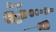
What are the 4 Modules of the T700 engine?
|
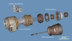
1) Cold Section Module
2) Hot Section Module 3) Power turbine Module 4) Accessory Section Module |
|
|
How many bearings support the Engine rotor system?
|
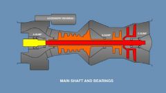
6 Bearings and 3 sumps.
#1- Ball (duplex) thrust(5-piece), Absorbs radial and axial loads- Output shaft #2- Roller (2 piece), obsorbs Radial loads- output shaft. #3- Ball ( 4 piece) thrust, Absorbs radial and axial loads-Gas generator Rotor #4- Roller(2 piece) Abosrbs Radial loads- Gas Generator Rotor #5- Roller (2 piece) Absorbs Radial loads- Power Turbine Rotor #6- Ball- (4 piece) thrust, Absorbs radial and Axial loads, Power turbine rotor. |
|
|
What does the Carbon and Labyrinth Seal Do?
|
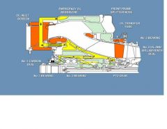
-Seal pressurization limits oil loss from the sumps by limiting airflow into them
-Pressurization keeps hot gasses, dust and moisture out of the sumps by providing a high pressure barrier. - Air is bled from the 4th Stage compressor to pressurize the A and B sump. |
|
|
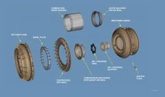
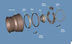
What components comprise the Cold Section?
|
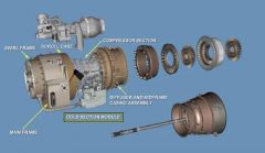
-Inlet Section
-Compressor Section -diffuser and midframe assembly |
|
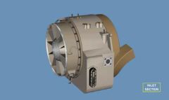
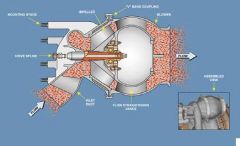
Within the Cold Section, What components comprise of the Inlet section?
|
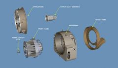
-Swirl frame
-Main frame -Output shaft. -Front frame -Scroll Case |
|
|
Cold Section- Inlet Section-
Describe the funtions of the Swirl Frame. |
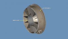
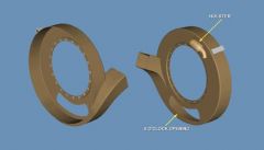
-Swirl frame, 12 fixed hollow swirl vanes, wash manifold located at 7 o'clock position, outer shell has tubing for oil supply/scavange for A-sump area.
|
|
|
Cold Section- Inlet Section-
Discribe the Main Frame. |
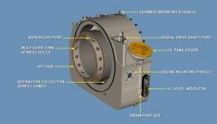
main frame- Seven integrally cast scroll veins, internally cored passages to allow oil to and from the A sump area and acc gear box, Accessory gear box attaches to the main frame, has 3 mounting pads, A port located at 130 o'clock.
|
|
|
Cold Section- Inlet Section-
Discribe the output Shaft. |
output shaft- Housed in the front frame, mounting surface for the #1 and #2 bearing, connects to the power turbine drive assembly, provides forward seal to the A sump
|
|
|
Cold Section- Inlet Section
Discribe the front Frame. |
-front frame-Enclosed within the main frame, 18 deswirl vanes, inner bore houses the output shaft assembly, PTO mounted at 1;30 O'clock position.
|
|
|
Cold Section- Inlet section
Discribe the Scroll Case. |
-scroll case- fiberglass, attaches to the main frame, flow path for FOD, driven by accessory mod, 6 o'clock opening provides cooling for ECU, contains T2 sensor for HMU
|
|
|
Cold Section- Compressor Section.
What two sections consist of the Compressor Section? |
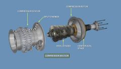
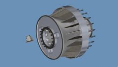
-Compressor Rotor
-Compressor Stator |
|
|
Cold Section- Compessor Section.
Discribe the Compressor rotor. |
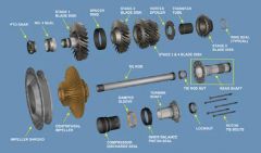
-5 Axial Stages
-1 Centrifugal Stage -Compressor max speed is 44,700 rpm -4 blade disks, centrifugal impeller, spacer ring, bleed air vortex spoiler, compressor tie rod. |
|
|
Cold Section- Compressor Section
Discribe the Compressor Stator. |
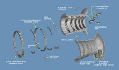
-Impeller shroud, part of the stator assembly, is assembled to the rotor during buildup and becomes trapped between impeller and blade disks.
- Compressor Casing contains stator vanes. -1st and 2nd Stages are variable stator veins -3rd 4th and 5th stage stator vanes are fixed. |
|
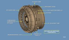
Cold Section-
Discribe the diffuser and Midframe Assembly. |
-Reduces speed of Centrifugal impeller airflow increasing air pressure
-Pressurized Air is directed to the diffuser Case. -Diffuser case directs air to the combustion chamber. -Ports are provided for attaching 12 fuel injectors, and 4 service tubes. |
|
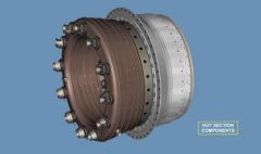
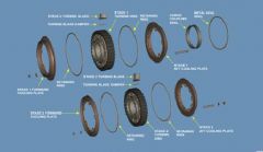
What components consist of the Hot Section?
|
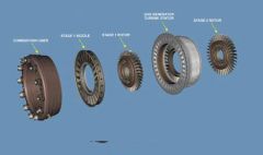
1) The Combustion Liner
2) The Stage 1 Nozzle assembly 3) 1st and 2nd stage gas gen turbine rotor. 4) Gas generator Stator. |
|

Hot Section-
Discribe the combustion liner. |
-Ring type combustor, cooled with secondary airflow from the diffuser case.
-uses a low pressure fuel injection system with vortex air swirlers to mix fuel and compressor discharge air prior to combustion -12 igniters are mouted in the midframe. -Each fuel injector inserts into the center of an air swirler in the dome liner. -For engine start, 2 spark igniters are incorperated. -combustor may be removed along with the rest of the hot section without removing the fuel injectors. |
|
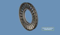
Hot Section
Discribe the Stage 1 Turbine nozzle. |
Directs Gas flow from the combustor discharge to the stage one and two gas generator turbine rotor and gas generator stator.
-Consists of 24 air cooled vanes, cast in pairs. -12 segments are assembled to the inner support. -Stage 1 turbine nozzle rotates. |
|
|
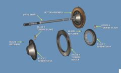
Hot Section
Stage 1 and 2 gas generator turbine rotor. |
-both stages air cooled.
-1st stage has 34 blades -2nd stage 38 blades |
|
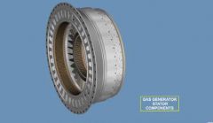
Hot Section
Discribe the Gas turbine Stator. |
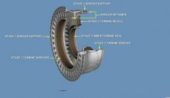
-13 Air cooled turbine nozzle segments, housed in the stator support.
-The Gas Gen Stator houses the stage 1 and 2 gas gen stator rotor and stage 2 turbine nozzle segments. |
|
|
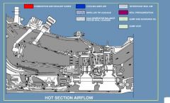
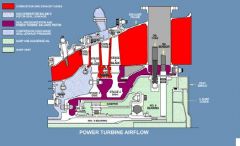
Hot Section
Discribe Air flow in the hot Section. |
|
|
|
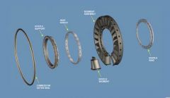
What components are within the power turbine module?
|
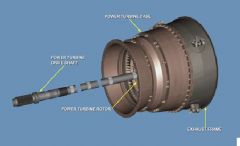
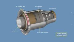
1) Turbine Case
2) Power Turbine Rotor Assembly 3) Power Turbine Drive Shaft Assembly 4) Exhaust Frame 5) C-Sump housing |
|
|
Power turbine Module
Discribe the Power turbine rotor assembly. |
-Consists of the 3rd and 4th Stage disks mounted on a drive shaft,
-Supported by the #5 and #6 bearings in the Rear and the output shaft assembly in the front. - |
|
|
Power Turbine Module
Discribe the Drive Shaft Assembly. |
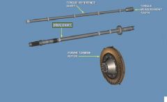
-Hollow and splined at forward end to attach to the output shaft, and attaches to the power turbine rotor disc in rear.
-TQ loading causes drive shaft to twist. -Drive shaft and refference shaft teeth draw closer together with increase of TQ, allowing a basis to measure TQ. -Sensors measure shafts for TQ and send signal to ECU. |
|
|
Power turbine Module
Discribe the Power Turbine Stator/Case. |
Provides housing for the power turbine rotor and stage 3 and 4 nozzle assemblies.
-Stage 3 nozzle is a one piece nozzle duct assembly. -Supports Thermalcouple assembly. |
|
|
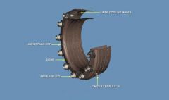
Power turbine Module
Discribe the Exahust Frame and C-Sump housing. |
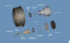
-Exhaust Frame Supports the C-Sump housing (4 struts)
-Provides housing for oil and scavage lines, and TQ and overspeed sensors. -Houses the #5 carbon seal -C sump contains oil jets, retaining ring, #5 bearing, damper piston ring, bearing support, #6 bearing, C sump cover, and heat shield. |
|
|
Power turbine Section
discribe Airflow within the Power turbine section. |
|
|
|
Accessory Section Module
What components are mounted to the from of the AGB? |
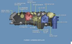
-Alternator
-boost Fuel Pump -Lube and scavange pump -chip detector -Oil cooler -Fuel and Lube Filters |
|
|
Accessory Section Module
What components mount to the Rear of the AGB? |
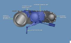
-Engine Starter
-HMU -inlet Partical Separator Blower -Overspeed and drain valve |
|
|
Accessory Sectoin Module
AGB Rear Explain the IPS Blower. |
Removes FOD from engine inlet air.
|
|
|
Accessory Sectoin Module
AGB Rear Explain the Starter Drive train. |
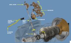
-PTO assembly drives the radial drive shaft, which thru drive train gearing, drives the AGB
-The Starter assembly is mounter to the AGB. |