![]()
![]()
![]()
Use LEFT and RIGHT arrow keys to navigate between flashcards;
Use UP and DOWN arrow keys to flip the card;
H to show hint;
A reads text to speech;
65 Cards in this Set
- Front
- Back
|
Introduction FLT CONTROLS |
The Flight Control System (FCS) is a functionally distributed Fly-By- Wire (FBW) control system The primary flight control system consists of: - Ailerons and multi-function spoilers for lateral (roll axis) control; - Elevators for longitudinal (pitch axis) control; - Rudder for directional (yaw axis) control. The secondary flight control system consists of: - Horizontal stabilizer; —Flaps; - Multi-function spoilers (when used as speed brakes or ground spoilers). The secondary flight control system includes the Pitch Trim Actuation System (PTAS) and Flap Actuation System (FAS).
|
|
|
SIDE STICK CONTROLLER |
AP QUICK DISCONNECT/PRIORITY SELECT (AP/PTY) BUTTON – When the priority button is pressed, the autopilot is automatically disengaged if active. The priority annunciation is activated only after 1 second of having the priority button pressed, in order to differ from the AUTOPILOT quick disengagement action. THERE IS A BREAKPUT FORCE THAT THE PILOT CANA COMMAND AND IT WILL DISCONNECT THE AUTOPILOT - This button gives exclusive control to the sidestick while pressed, inhibiting the inputs from the cross-side sidestick to be transmitted to the controls. Depending on the time the button is held down, two results are possible as follows: PRIORITY BUTTON: If the priority button is held down for more than 20 seconds, the respective sidestick will have exclusive control TO RELEASE PRIORITY,: MAINTAINS PRIORITY until the cross-side sidestick priority button is pressed or the priority button of the sidestick in exclusive control is released and pressed again; If the priority button is held down for less than 20 seconds and released, the sidestick authority reverts to the algebraic sum of the two stick inputs. - If dual sidestick input occurs, the output is the algebraic sum of both pilots’ sidestick inputs. The FCC limits this sum to the maximum command of a single sidestick. – If dual sidestick input occurs and priority has not been requested by any pilot, a tactile warning in both sidesticks is activated, as well as a dual input aural warning and a visual announcement on PFD are triggered.
- If the priority button fails, the respective sidestick will not be able to request exclusive control; NOTE: The sidestick controller NM priority logic described above is not available in DM. |
|
|
SIDE STICK CONTROLLER: TOUCH CONTROL STEERING (TCS) BUTTON
|
– While pressed, with the AP engaged, it momentarily allows the pilots to manually control the airplane without AP disengagement or AP mode change. After button release, the AP returns to the previous engaged mode. - During manual flight with flaps 3 or FULL and gear down, the pilots are capable of resetting the TCS trim speed bug, in order to re-trim the horizontal stabilizer in relation to the airplane speed, when the button is released. - The TCS trim synchronizes the airplane current airspeed when the TCS button is pressed indicating the approach TCS trim control law (flaps 3 or FULL and with landing gear down) activation. The control law activation is indicated through a TCS TRIM green flag displayed beneath the speed tape (refer to AOM Section 9-09-30 AIRSPEED INDICATION).
|
|
|
FLAP SELECTOR LEVER
|
Lever Position/Flap Position
0/0 position 1/7 deg 2/ 21 deg 3/21 deg Full/37 deg
– Intermediate positions are not enabled. If the lever is left at an intermediate position, flaps remain in the last selected position. |
|
|
SPEED BRAKE LEVER
|
All multi-function spoilers’ panels are proportionally deployed, in a continuous response to the speed brake lever position. If the lever is left at an intermediate position, the speed brake panels will assume an angle between 0° (stow) and 30° (full). |
|
|
FLIGHT CONTROLS SYSTEM/TRIM PANELS
|
PITCH TRIM SWITCH: For trim purposes there is a dual switch for pitch axis trim adjustment. Both switches must be simultaneously actuated in the same direction to provide command to the PTS. – The PTS can be manually commanded only on ground or in DM. Yaw Trim Knob: normal ops |
|
|
FLTCTRL NORMAL MODE BUTTON (GUARDED)
|
A FLTCTRL NORMAL MODE button installed on center pedestal panel to recover NM or to revert to DM in case of NM misbehavior. Manual reversion to DM is inhibited while the following FCS envelope protections are engaged: Low speed protection; |
|
|
FLIGHT CONTROLS SYNOPTIC PAGE
|
The flight controls synoptic page on the Multi Function Window (MFW) provides flight crew with the control surfaces position, actuators status, surface awareness and electrical and hydraulic Power-up Built-in Test (PBIT) expire time. This synoptic page is selected through the Cursor Control Panel (CCP) which comprises the trackball. The pictorial rear view of the airplane enables the crew to easily recognize the surface position with respect to the neutral and maximum positions. A rectangle represents the surface position range and will be filled up proportionally to the deflection of the surface. Each control surface has a surface range scale. When the surface is fully deployed, the control surface range scale and the filled rectangle will be at the same level. A red X indication in the surface position area indicate the surface data is invalid. Also, the system layout on the display provides a mean of easily identifying the complete system status, which allows the flight crew to quickly recognize system condition. The surface positions displayed on the flight controls synoptic on MFW is available in Normal Mode (NM) and Direct Mode (DM).
|
|
|
PITCH/YAW TRIM INDICATION
|
– GREEN: Position is valid and available. – RED (inverse video): Before takeoff, pitch trim position is outside of the green band. PITCH TRIM GREEN BAND |
|
|
FLIGHT CONTROLS INDICATIONS ON PFD
|
The following flight controls indications are displayed on PFD: – Sidestick priority; |
|
|
FLIGHT CONTROLS INDICATIONS ON PFD : SIDESTICK PRIORITY
|
The Sidestick priority indication indicates which sidestick is on command and warns the crew of dual sidestick input, combined with an aural and tactile warning.
BOTH SIDESTICKS COMMANDED AT THE SAME TIME (NO PRIORITY REQUEST) WARNINGS Indicated on PFD 1 and PFD 2 DISPLAY , AURAL WARNING: DUAL INPUT TACTILE WARNING: ON
PRIORITY REQUESTED BY THE PILOT (Captain) - STICK PTY STICK PTY shows on PFD 1 and 2 and has an arrow pointing to the Captain Position - AURAL WARNING: PRIORITY LEFT, TACTILE WARNING: OFF
PRIORITY REQUESTED BY THE COPILOT
STICK PTY STICK PTY indicated on PFD 1 and 2 with an arrow pointing to the copilot AURAL WARNING: PRIORITY RIGHT, TACTILE WARNING: OFF NORMAL OPERATION (NO PRIORITY REQUEST)
AURAL WARNING: − TACTILE WARNING: OFF
|
|
|
FLIGHT CONTROLS INDICATIONS ON PFD: SIDESLIP TARGET |
The sideslip target is a required yaw command, presented by a blue slip-skid indicator, in a One Engine Inoperative (OEI) condition during the takeoff, climb and go-around flight phase. |
|
|
FLIGHT CONTROLS INDICATIONS ON PFD: LOW SPEED AWARENESS AND PITCH LIMIT INDICATOR
|
The LSA, adjacent to the speed tape, and the PLI, always parallel to the attitude reference airplane symbol on the Attitude Direction Indicator (ADI), alerts the flight crew of a low speed condition. In Normal Mode (NM), the AOA limiter function is operational and the LSA indicates:
- VSS: Represented by the top of the white tape and indicates the low speed protection function and should be close to 1.13 VS1G. In landing flap configurations, it indicates the minimum airspeed the aircraft can be trimmed at. In the other flap. configurations, it indicates the addition of speed stability; – VAOA: Represented by the top of the amber tape and indicates the AOA limiter function activation (1.08 VS for 1 g conditions). This is the AOA limiter protection; – VLIM: Represented by the top of the red tape and indicates the speed associated with the maximum allowable AOA airspeed (1.03 VS for 1 g conditions). Since VSS is defined in terms of speed and VAOA/VLIM are defined in terms of angle of attack, those indications have different behavior in curves and other maneuvers. The white tape is not affected by load factor variation, so that it does not change when the aircraft is maneuvered into or out of a curve. On the other hand, VAOA/VLIM will increase if the aircraft is maneuvered into a curve and the yellow tape may cover the white tape in this condition. - In Direct Mode (DM), the AOA limiter function is not operational and the LSA is modified to maintain correspondence with the stall aural alert. There are two airspeed indication: Where: – VSA: Represented by the top of the red tape and indicates the airspeed at which the stall aural alert message is triggered (1.10 VS); – VMS: Represented by the top of the amber tape and indicates an airspeed with appropriate margin to VSA (1.15 VS).
The LSA, adjacent to the speed tape, and the PLI, always parallel to the attitude reference airplane symbol on the Attitude Direction Indicator (ADI), alerts the flight crew of a low speed condition. In Normal Mode (NM), the AOA limiter function is operational and the LSA indicates:
- VSS: Represented by the top of the white tape and indicates the low speed protection function and should be close to 1.13 VS1G. In landing flap configurations, it indicates the minimum airspeed the aircraft can be trimmed at. In the other flap. configurations, it indicates the addition of speed stability; – VAOA: Represented by the top of the amber tape and indicates the AOA limiter function activation (1.08 VS for 1 g conditions). This is the AOA limiter protection; – VLIM: Represented by the top of the red tape and indicates the speed associated with the maximum allowable AOA airspeed (1.03 VS for 1 g conditions). Since VSS is defined in terms of speed and VAOA/VLIM are defined in terms of angle of attack, those indications have different behavior in curves and other maneuvers. The white tape is not affected by load factor variation, so that it does not change when the aircraft is maneuvered into or out of a curve. On the other hand, VAOA/VLIM will increase if the aircraft is maneuvered into a curve and the yellow tape may cover the white tape in this condition. - In Direct Mode (DM), the AOA limiter function is not operational and the LSA is modified to maintain correspondence with the stall aural alert. There are two airspeed indication: Where: – VSA: Represented by the top of the red tape and indicates the airspeed at which the stall aural alert message is triggered (1.10 VS); – VMS: Represented by the top of the amber tape and indicates an airspeed with appropriate margin to VSA (1.15 VS) |
|
|
FLIGHT CONTROLS INDICATIONS ON PFD: PITCH LIMIT INDICATOR
|
- The PLI, displayed on the pitch angle scale, indicates the margin to VAOA and VLIM when in NM. |
|
|
FLIGHT CONTROLS AURAL WARNINGS
|
AURAL WARNING MESSAGE DUAL INPUT: Both sidesticks commanded at the same time. PRIORITY LEFT: Priority requested by the left seat pilot. PRIORITY RIGHT: Priority requested by the right seat pilot. |
|
|
Flight Controls: memory Items
|
Flight Control switch( off) |
|
|
FLY-BY-WIRE (FBW) |
FBW is an electronic system designed to operate the flight controls replacing the control cables of a conventional airplane. The Legacy 500 FBW system provides closed-loop control and monitoring of all primary and secondary flight control surfaces within the system. In a closed-loop control system, a sensor monitors the system output (e.g. the actuator’s position) and feeds the data back to a controller which adjusts the control (e.g. the actuator) as necessary to maintain the desired system output (e.g. match the actuator’s position to the reference position). |
|
|
FLIGHT-BY-WIRE COMPONENTS |
The Legacy 500 FBW architecture is structured around four separated stick-to-surface control paths. Each control path consists of:
|
|
|
INCEPTOR INTERFACE MODULE (IIM) |
The basic IIM function is to transmit digital data from the cockpit interfaces listed below to the FCC and REU. The cockpit interfaces are as follows:
|
|
|
|
|
|
|
FLIGHT CONTROL COMPUTER (FCC) |
The FCC hosts the following functions:
|
|
|
|
Each primary surface is controlled by two EHA in active-active configuration. The primary surface hydraulic actuators have two modes of operation as follows: – Active; – Damped bypass.
primary surface is lost due to a common cause REU failure.
|
|
|
ELECTRO-MECHANICAL ACTUATORS (EMA) |
There are EMA for the following systems:
|
|
|
|
|
|
|
FLAP ACTUATOR SYSTEM (FAS) |
The FAS is composed by two flap surfaces per wing, named inboard (IB) and outboard (OB) flap surfaces. There are three flap linear actuators per wing. The OB flap surfaces are driven by two flap actuators each, while the IB flap surfaces are driven by one flap actuator each, and they are interconnected by a driveline composed by eight flap flexible shafts in the airplane. A Power Drive Unit (PDU) drives the drive line and the actuators.
Electrically, the FAS is a dual channel control architecture commanded independently by two different REU types and respective MCE channels to provide a high integrity REU/MCE command path for each flap PDU motor. |
|
|
FLIGHT CONTROL SYSTEM (FCS) INTERFACES |
The FCS also interfaces through data buses with other airplane systems as follows: Avionics system:
– Two Full Authority Digital Engine Control (FADEC). Brake control system: Landing gear system: Air management system: Electric system:
|
|
|
MODES OF OPERATION
|
|
|
|
NORMAL MODE VERSUS DIRECT MODE SELECTION |
NORMAL MODE VERSUS DIRECT MODE SELECTION The system is designed in a way that all the primary surfaces are always in the same FCS operational mode. In case both actuators on a primary surface are not able to operate in NM, the FCS maintains NM only if it identifies that the surface is also not recoverable in DM (not DM capable). The FLTCTRL NORMAL MODE button installed on the central console allows NM recovery when FCS is NM capable. In case of NM misbehavior, this button may be used to revert the FCS to DM, as long as no FCS protection function is active. NOTE: The flight under DM should be avoided as some airplane protection functions are only available in NM. he FCS reverts automatically to DM operation when it is not possible to keep the NM operation due to multiple system failures, which affected the availability of the essential sensors (flap position, ADSP or AHRS data) or the internal FCC integrity. |
|
|
FCS BUILT-IN TEST |
STARTUP BUILT-IN TEST The SBIT is a basic core processing capability test, applicable to IIMs, REUs, MCEs and FCCs to ensure that the unit has been correctly started-up and to determine the airplane configuration and unit position. The SBIT duration time does not exceed 10 seconds, and is automatically performed at every power-up, no matter the airplane is in the air or on the ground. Also, it does not prevent the in-air power-up time requirements from being achieved. POWER-UP BUILT-IN TEST The PBIT automatically tests the FCS at each power-up under FCC control in order to ensure the FCS is correctly configured and to reduce the FCS component’s exposition to latent faults. Each PBIT operation takes less then 1 minute, and if conditions are not satisfied, the FCS automatically perform another PBIT operation, up to three times, before declaring a failure, extending the PBIT to approximately 4 minutes. During the PBIT operation, the FLTCTRL TEST IN PROG CAS message is displayed. If the PBIT operation does not pass or a failure is detected, the FLTCTRL TEST FAIL CAS message will be displayed. In this case, the Onboard Maintenance System (OMS) shall be checked. If the PBIT operation is interrupted, the PBIT TIME EXPIRED CAS message will be displayed and the airplane must be powered down and then powered up to run the PBIT again. The system keeps track of the hours interval between successful PBIT completions and prompts PBIT execution through the PBIT TIME EXPIRED CAS message when such interval exceeds the limit set by safety analysis, which corresponds to 20 hours starting at each airplane power up. When this CAS message is displayed, a new successful PBIT is required to clear this message. The PBIT comprises the following tests:
|
|
|
FCS BUILT-IN TEST The PBIT comprises the following tests:
|
ELETRICAL POWER-UP BUILT-IN TEST The FCC initiates the electrical PBIT after airplane power up provided that:
Control laws Flight controls 9-08-40 page 20
|
|
|
FLY-BY-WIRE CONTROL LAWS |
The CLAWS are a set of functions, named closed-loop functions, that computes the control surfaces commands based on airplane sensors data, airplane configuration and pilots’ inputs through the sidestick controllers and the rudder pedals. Due to these closed-loop functions (CLAWS), pilots’ commands are interpreted as demands for airplane response rather than surface deflection. In this sense, the CLAWS command the surfaces so that the airplane achieves the desired response. |
|
|
FLY-BY-WIRE CONTROL LAWS: NORMAL MODE FUNCTIONS |
NORMAL MODE FUNCTIONS The NM provides automatic compensation for thrust variations, landing gear and different flap configurations, and provides the same flight characteristics for different weights, CG positions and speeds. There is damped airplane response during turbulence, minimizing airplane oscillations; reduced transient in case of a system failure such as engine shutdown or surface hardover, so that the airplane controllability is easier, letting the flight crew have clear indications/cues of the failure.
In-flight, there is no manual command to PTAS, only automatic pitch trim compensation controlled by the CLAWS. On ground, the manual command to PTAS is available. |
|
|
NORMAL MODE FUNCTIONS; AXIS CONTROL FUNCTIONS AND PROTECTION FUNCTIONS
|
Pitch Axis- CONTROL FUNCTIONS AND FEATURES – Longitudinal neutral stability command; – Pitch damper;
PITCH AXIS- PROTECTION FUNCTIONS
Roll Axis-CONTROL FUNCTIONS AND FEATURES
- Roll rate command; – Neutral spiral stability, positive spiral stability for large bank angle; – Automatic lateral compensation with sideslid. ROLL AXIS- PROTECTION FUNCTIONS
Yaw Axis- CONTROL FUNCTIONS AND FEATURES Sideslid command; – Yaw damper (on ground); – Yaw trim (sideslip command);
YAW AXIS - PROTECTION FUNCTIONS
Lift Dump - CONTROL FUNCTIONS AND FEATURES - Speed brake; – Ground spoilers.
|
|
|
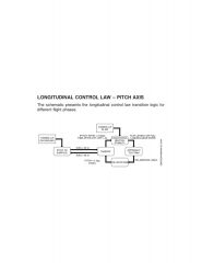
LONGITUDINAL CONTROL LAW TRANSITION LOGIC DIAGRAM
|
|
|
|
LONGITUDINAL CONTROL LAW TRANSITION LOGIC; STICK TO SURFACE CONTROL LAW
|
The stick to surface control law is activated when the airplane is on ground and up to 65 kt on the takeoff roll. In this control law, there is a stick to surface direct link with no augmentation (no airspeed gain schedule) and without autotrim, which means that there is a direct relationship between the sidestick controller and elevator deflection irrespective of the airplane airspeed. The takeoff trim is manually set via the pitch trim switch located on the center pedestal. The reverse process occurs after touchdown.
|
|
|
LONGITUDINAL CONTROL LAW TRANSITION LOGIC: TAKEOFF CONTROL LAW |
The takeoff control law as well as the pitch dumper function is active when the airspeed is greater than 65 kt during takeoff roll. The control law receives a pitch rate demand as a function of the aft sidestick deflection, providing precise capture of pitch angle after lift off and standardizing the airplane response for different weights and CGs. At full aft position, the sidestick provides 15° per second of pitch rate demand without auto trim. |
|
|
LONGITUDINAL CONTROL LAW TRANSITION LOGIC: LONGITUDINAL NEUTRAL STABILITY CONTROL LAW |
The longitudinal neutral stability control law is a flight path demand mode which is active 5 seconds after airplane lift off with the pitch rate less than 2° per second. In this mode, the airplane becomes flight path stable rather than speed stable, and the control law response remains almost unaffected by the weight or CG shift. The longitudinal neutral stability control is active after takeoff until landing, where the de-rotation control law is active.
|
|
|
LONGITUDINAL CONTROL LAW TRANSITION LOGIC: APPROACH TCS TRIM CONTROL LAW |
The approach TCS trim control law adds speed stability to the longitudinal neutral stability control law, becoming active when the landing gear is down and the flap is set to 3 or FULL position with the AP disengaged. The control law activation is indicated through a TCS TRIM green flag below the airspeed tape. NOTE: The speed stability control law will also engage in case of flap and/or landing gear failure. Upon control law activation, the auto trim function is not available and the airplane must be manually trimmed via the TCS button. Refer to AOM Section 9-09-30 AIRSPEED INDICATION. When the TCS button is pressed, the airplane is trimmed to the current airspeed and the TCS trim bug is displayed. The airplane will maintain the load factor and stall protection, restoring the trimmed airspeed in case of atmospheric turbulence and sidestick controller deflection until a new airspeed is selected through the TCS button. The TCS trim reference speed is limited at the low speed awareness activation. The airplane flare is accomplished by pulling the sidestick controller back as required in order to reduce the airplane airspeed, providing conventional flare characteristics without using the radio altimeter data. The approach TCS trim control law is active until airplane touchdown. |
|
|
LONGITUDINAL CONTROL LAW TRANSITION LOGIC: DE-ROTATION CONTROL LAW |
The de-rotation control law is active when the airplane touchdown, providing a smooth nose down movement by commanding the elevator to a nose down pitch rate of 2° per second when the sidestick controller is set to the neutral position. - The airplane will transition back to takeoff control law when the airplane pitch is less than 2° and then to stick to surface control law when the airplane airspeed is less than 65 kt during the landing roll. If a go around is required, the crew must press the TO/GA button on the power quadrant.
In case of bounced landing, the airplane will transition from the de-rotation law back to approach TCS trim control law, with the elevator trimmed for the last approach speed set prior to the flare. If a go around maneuver is required, as the landing gear and flaps are retracted, the airplane will transition to the takeoff control law and then to the longitudinal neutral stability control law. |
|
|
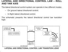
LATERAL AND DIRECTIONAL CONTROL LAW – ROLL AND YAW AXIS |
|
|
|
ON GROUND LATERAL AND DIRECTIONAL CONTROL LAW -YAW DAMPER |
The lateral and directional ground mode is activated when the airplane is on ground or 2 seconds after touchdown. The lateral control command is generated through a direct link between the sidestick controller and the ailerons and spoilers surfaces, as well as the directional control command is generated through a direct link between the pedals and the rudder surface. YAW DAMPER-
|
|
|
|
- The in-flight lateral and directional control is provided by the neutral spiral stability control law, based on the lateral sidestick controller and pedal deflection and activated after airplane lift off. - The amount of aileron, spoiler and rudder control surface deflection that results from the sidestick controller and pedals deflection depends upon:
|
|
|
NEUTRAL SPIRAL STABILITY CONTROL LAW : to maintain the flight level during turns up to 33° of bank angle.
|
After a sidestick controller roll rate command, the neutral spiral stability control law automatically trims the elevator when the sidestick controller is set back to the neutral position, to maintain the flight level during turns up to 33° of bank angle. |
|
|
POSITIVE SPIRAL STABILITY CONTROL LAW : Bank angles > 33dg with sidestick neutral rolls aircraft back to 33 deg bank angle |
The positive spiral stability control law is provided for bank angles beyond 33° with the sidestick controller at neutral position. The control law starts to add an amount of spiral stability proportional to the difference between the actual bank angle and the 33° reference bank angle, rolling the airplane back to 33° when the sidestick controller is set to the neutral position, providing a soft limit envelope protection. At 33° bank angle, the control law transition back to the neutral spiral stability control law. - The amount of spiral stability applied is proportional to the bank angle beyond 33°, and inversely proportional to the sidestick deflection. Increasing the sidestick controller lateral deflection towards the lateral stop, the amount of spiral stability is proportionally decreased and, at the stop, the amount of spiral stability added is null. The maximum roll rate capability is achieved by setting the sidestick controller at the lateral stop. - commanding a bank angle > 33 deg will require a constant lateral pressure from the sidestick and in order to maintain altitude, you will need to move the sidestick rearward commanding the elevator to pitch up - This feature combined with automatic pitch compensation up to 33° of bank allows safe recovery from roll upset by returning the stick to the neutral position.
|
|
|
SIDESLIP TARGET |
The sideslip target is activated in a OEI condition during the takeoff, climb and go-around flight phase and changes the slip-skid indicator color from white to blue. The control law generates a sideslip indication through the slid-skid indicator proportional to the residual sideslip. - The residual yaw and bank angle can be compensated by applying rudder and sidestick controller in order to maintain airplane heading and improve climb gradients. The required amount of rudder or pedal deflection to counteract the residual OEI yaw moment is provided by centering the roll scale and the slip-skid indicator. - NOTE: At full range, the sideslip indicator color will change from blue to yellow.
|
|
|
LIFT DUMP FUNCTION |
The lift dump function of lift dump, airplane drag increase, and steeper angle of descent creation, is implemented in the FCC. The lift dump function increases the airplane drag and provides a steeper angle of descent. The lift dump functions are as follows:
|
|
|
LIFT DUMP FUNCTION: SPEED BRAKE (test question) |
The speed brake control is provided by the speed brake lever. The three pair of multifunction spoiler panels are symmetrically deployed at the same angle, varying from 0° (stow) to 30° (full), according to the speed brake lever position. The speed brake function is enabled provided that:
-If any of the above conditions are removed with the speed brake deployed, the control law generates a command to retract the speed brake with its lever in the deployed position, and displays the SPDBRK LEVER DISAG CAS message. In this case, the speed brake lever must be set back to the CLOSE position, to clear the CAS message and allowing the speed brake reactivation. |
|
|
LIFT DUMP FUNCTION:
GROUND SPOILERS |
When the ground spoiler function is activated, all multifunction spoiler panels are commanded to the full deployed position (40°).
The ground spoiler function operates in four different modes:
|
|
|
LIFT DUMP FUNCTION:
FLAP 3 WITH SPOILER FUNCTION |
This function provides lift dump and increases the airplane drag in order to assist the pilot to maintain the airspeed and trajectory while performing landing with flap 3 configuration. When this function is activated, the three pair of spoilers is commanded to 15°. The flap 3 with spoiler function is activated when the following conditions are met:
If any of the above conditions are removed when the spoilers are already deployed for the flap 3 with spoiler function, the control law commands the multifunction spoilers back to the retracted position. |
|
|
FLIGHT CONTROL NORMAL MODE MISBEHAVIOR |
A flight controls NM misbehavior is any airplane behavior that the flight crew realize it is behaving unexpectedly, not responding adequately to the commands or is presenting lack of response. - A manual reversion to DM is available in case the flight crew identifies a flight control NM misbehavior. Under this scenario, the pilot shall press the FLTCTRL NORMAL MODE button in order to revert the FCS to DM (refer to AOM Section 4-02-01 FLTCTRL N-MODE MISBEHAVIOR Non Annunciated). - The reversion to DM is indicated through a > FLTCTRL N-MODE FAIL CAS message followed by a triple chime aural warning. The FCS synoptic page presents the control surfaces in yellow and the airplane looses the auto trim capability, besides the different piloting characteristics (control to surface). - However, if the airplane is flying inside the low speed, AOA limiter or high speed envelope protection, the FLTCTRL NORMAL MODE button is inhibited, precluding the DM engagement. This will be immediately noticed by the absence of > FLTCTRL N-MODE FAIL CAS message. The PFD will also keep displaying the white tape and PLI (if inside AOA limiter) in case of a low speed and high AOA scenario. - The flight crew must wings level, trim the airplane and assure the airplane is in a safe altitude before attempt to recover NM by pressing the FLTCTRL NORMAL MODE button.
|
|
|
FLIGHT ENVELOPE AND PROTECTION FUNCTIONS |
The CLAWS also provides flight envelope protections to prevent the airplane from exceeding the flight envelope limitation, by calculating the appropriate control surface deflections in order to maintain the airplane inside the limits. There are two flight envelopes for the airplane:
|
|
|
FLIGHT ENVELOPE AND PROTECTION FUNCTIONS : NORMAL FLIGHT ENVELOPE |
|
|
|
FLIGHT ENVELOPE AND PROTECTION FUNCTIONS : HIGH SPEED PROTECTION |
The control law automatically recovers by commanding an additional load factor proportional to the difference between the current speed and the maximum operating speed, limited to 1 g, towards the VMO when the airspeed limit of VMO + 6 kt or MMO + 0.01 is exceeded. - The pilot sidestick controller nose down authority is reduced during the recover maneuver, but if a full forward sidestick controller deflection is commanded, the airspeed is limited to VMO + 22 kt. Positioning the sidestick controller to the neutral position, the airplane returns to the normal flight envelope, maintaining the load factor and AOA (stall) protection. - A visual warning comprised by an emphasized VMAX marker (barber pole) shall be already in view before the airplane reaches the VMO, and the airspeed digits (knots and Mach) become red inverse video indicates that the current airspeed becomes greater than VMO (refer to AOM Section 9-09-30 AIRSPEED INDICATION). A HIGHSPEED aural warning continually sounds when the airspeed is greater than VMO + 4 kt.
|
|
|
FLIGHT ENVELOPE AND PROTECTION FUNCTIONS : LOW ENERGY AVOIDANCE PROTECTION |
The low energy avoidance provides adequate low energy awareness to the pilot, ensuring that the airplane will not inadvertently reach speeds significantly below the normal operating speeds. The system is comprised of Low Speed Protection and Low Speed aural Warning. - The low speed protection function is activated when the speed becomes lower than a value of approximately 1.13 times the stall speed, represented by the top of the white tape (VSS). In landing flap configurations, it indicates the minimum speed the airplane can be trimmed at. In the other flap configurations, it indicates the addition of speed stability to the longitudinal control law. - When the autopilot is engaged, the autothrottle (if installed) will automatically engage slightly above VSS in order to prevent the airspeed to reduce below the top of the white tape. A stabilized flight within the white tape range will only be possible with an aft sidestick controller deflection, commanding the airplane to a pitch up attitude and decreasing the airspeed to a value smaller than VSS. - Positioning the sidestick controller back to the neutral position, the airplane will return to VSS. The TCS trim reference speed is also limited at VSS. A LOW SPEED aural warning is also provided to get the pilots attention to a low energy condition. The aural warning is activated when the airspeed is reduced to VSS and is interrupted when it is increased above this value. Below 2000 ft AGL, the low speed aural warning may be anticipated or activated with the airplane airspeed above VSS based on the following condition:
– If a high rate of energy loss is detected represented by the airspeed trend vector; – If an altitude loss is detected based in a glide slope deviation.
NOTE: A barometric altitude reference of 16000 ft and below is considered, instead of 2000 ft AGL, in case of radar altimeter failure. - The aural warning is inhibited in case the throttles are close to TO/GA and/or when radar altimeter is below 100 ft AGL.
|
|
|
FLIGHT ENVELOPE AND PROTECTION FUNCTIONS : PITCH ATTITUDE PROTECTION |
The pitch attitude protection is an additional function to increase the effectiveness of the stall and high speed protections, and activates at pitch angles of:
|
|
|
FLIGHT ENVELOPE AND PROTECTION FUNCTIONS: LIMIT FLIGHT ENVELOPE |
- Outside the normal flight envelope, there is the limit flight envelope. The limit flight envelope represents the condition in which the airplane is close to the envelope hard limits, thus requiring more pilot effort to maintain the airplane in this condition. - The pilot is not able to override the hard limits, and if the sidestick controller is released, the airplane is brought back to the normal flight envelope.
- The external boundaries of the limit flight envelope are reached at full control application. The hard limits of this flight envelope are:
|
|
|
FLIGHT ENVELOPE AND PROTECTION FUNCTIONS: ANGLE OF ATTACK (AOA) LIMITER PROTECTION |
The AOA limiter protects the airplane from low speed stall and high Mach buffeting, and is activated when the angle of attack becomes greater than a value which corresponds to approximately 1.08 times the stall speed, represented by the top of the yellow tape (VAOA), engaging the AOA limiter control law.
The aft sidestick controller deflection corresponds to an angle of attack demand instead of load factor demand, and the control law will command the elevators to achieve the demanded angle of attack. Full aft sidestick controller deflection corresponds to the maximum commanded angle of attack (VLIM), which is approximately 1.03 times the stall speed represented by the top of the red tape. The control law allows the pilot to maintain the angle of attack limit at full aft sidestick controller deflection, providing adequate roll maneuverability, good flight characteristics, and enough margins to the stall (CLMAX). If the pilot sets the sidestick controller to the neutral position, the control law will command the airplane back to the VAOA, preventing the airplane from stalling. |
|
|
FLIGHT ENVELOPE AND PROTECTION FUNCTIONS: LOAD FACTOR PROTECTION |
The control law commands the elevator to maintain the load factor proportional to the sidestick deflection, airplane airspeed and flap configuration. The load factor is limited as follows: – Flap up:-1g to 2.5g; NOTE: Full forward stick command equal to -0.2 g, becoming -1 g in 3 seconds if full forward sidestick is maintained. – Flap down:0g to 2g for flaps down. |
|
|
FLIGHT ENVELOPE AND PROTECTION FUNCTIONS: MAXIMUM SIDESLIP
|
MAXIMUM SIDESLIP: As the pedal position corresponds to a sideslip command, the control law provides directly a sideslip limiter function. The sideslip angle is limited with the pedals at the stops. |
|
|
FLIGHT ENVELOPE AND PROTECTION FUNCTIONS: DIVE SPEED (VD)
|
The control law does not allow the airplane to exceed the maximum dive speed of Vd/Md equal to 360 kt/.90 M. |
|
|
THRUST ASYMMETRY TRANSIENT REDUCTION |
THRUST ASYMMETRY TRANSIENT REDUCTION In OEI condition, the control law automatically compensates almost all the yaw moment generated by the operating engine, providing only a residual sideslip and bank angle for the pilot to recognize the OEI condition and which engine is inoperative. NOTE: If no pilot action is taken, the airplane will slowly diverge the heading on a stabilized sideslip angle and bank angle condition. The OEI condition is detected if all the following conditions are satisfied:
|
|
|
DIRECT MODE FUNCTIONS normal mode direct mode Ultimate backup |
- The FCS automatically reverts to DM operation when data availability from the flap position, ADSP or AHRS to both FCC is affected due to system failure or the FCC integrity required to maintain NM CLAW is also affected. - The DM functions are classified as control functions/features and protection functions, as presented in the following table: Pitch Axis: CONTROL FUNCTIONS AND FEATURES - Surface command - Manual stabilizer trim Pitch Axis: PROTECTION FUNCTIONS - Stall aural alert elevator gain schedule
Roll Axis: CONTROL FUNCTIONS AND FEATURES – Surface command Roll Axis: PROTECTION FUNCTIONS - Aileron and spoilers gain schedule Yaw Axis: CONTROL FUNCTIONS AND FEATURES - Surface Command - Yaw Trim (rudder command) - Yaw Damper
Yaw Axis: PROTECTION FUNCTIONS - Rudder gain schedule
Lift Dump: CONTROL FUNCTIONS AND FEATURES
- Speedbrake (if FCC is available) - Ground spoilers (if FCC is available)
Lift Dump: PROTECTION FUNCTIONS - none
In DM, the airplane behaves like a conventional airplane, and the sidestick controller and pedal deflections are directly related to the surfaces position, limited by the airplane airspeed and flap position or, in case of loss of air data, only flap position information (ultimate backup). - Furthermore, the automatic pitch trim is not available in DM, and the airplane has to be manually trimmed in-flight and on ground via the PTAS. The yaw damper is present for both in air and on ground. NOTE: The AP is not operational in DM. The DM can be hosted in either FCC or REU. When the FCS DM is running in the FCC, it is referred to as FCC DM. When the FCS DM is running in the REU, it is referred to as REU DM. - In FCC DM, the FCC continues to process the available flap position, ADSP or AHRS sensors, the sidestick controller lateral deflection (aileron) and speed brake control lever inputs through the same data path as in NM. Thus, the MFS control is available for all three roll, speed brake and ground spoiler functions. In REU DM, the MFS control for speed brake and ground spoiler functions are not available, however MFS roll command is kept operational.
|
|
|
DIRECT MODE PROTECTION FUNCTION |
DIRECT MODE PROTECTION FUNCTION The following protections are provided in DM:
|
|
|
CAS MESSAGES:
WARNING: 2: - FLTCCTRL N-MODE FAIL - SIDESTICK LH(RH) FAIL |
WARNING: - > FLTCTRL N-MODE FAIL:Loss of NM, including the following main functions: required yaw command, AOA limiter, longitudinal neutral stability, auto trim, autopilot. - SIDESTICK LH (RH) FAIL: Loss of LH (RH) sidestick
|