![]()
![]()
![]()
Use LEFT and RIGHT arrow keys to navigate between flashcards;
Use UP and DOWN arrow keys to flip the card;
H to show hint;
A reads text to speech;
140 Cards in this Set
- Front
- Back
|
Max Gross Weight of 225? |
11,000 kg |
|
|
Max Weight on the Sling? |
3,000 kg |
|
|
Max overall width of 225? |
16.2 m (Rotor Diameter) |
|
|
Max height of 225? |
4.97 m |
|
|
D Value of 225 |
19.5 m |
|
|
Wheel tracking width |
3 m |
|
|
Minimum permissible weight of 225? |
6500 kg |
|
|
FADEC stands for? |
Full Authority Digital Engine Control |
|
|
On touchdown, the skid shoe will contact at....? |
12 degrees |
|
|
Total fuel capacity WITHOUT EFT's |
2297 kgs |
|
|
A blue light on a cockpit switch or panel indicates? |
Correct Position |
|
|
A system panel 'Latch' type switch that has a Yellow and White light illuminated within the switch indicates? |
The system is switched off. |
|
|
A Blue & White illuminated switch labeled GPU indicates? |
The GPU is available but NOT authorised. |
|
|
A yellow latch switch in the overhead console indicates? |
The system has failed OR is not online. |
|
|
A BLUE illuminated switch in the overhead console indicates? |
The GPU power is available AND operating the aircraft systems. |
|
|
A green light on a switch or system panel indicates? |
Normal system operation. |
|
|
In the event of CAUTION +HYD caption illuminating, the correct action to take would be: |
Check the VMS VEHICLE page for a Hyraulic systems caption or parameter, cancel the CAUTION, consult the checklist. |
|
|
The captions that can be extinguished by cancelling the amber CAUTION attention getter on the CWP are: |
HYD FUEL XMSN FIRE DET ENG |
|
|
How is the ELEC caption on the CWP extinguished? |
By selecting the failed electrical system OFF |
|
|
In the VMS, failure of EID 1, and following reconfiguration, will result? |
In EID 2 defaulting to the ENGINE page. |
|
|
Soft keys on an MFD are active... |
For those functions which they are labeled. |
|
|
To permit accurate fuel capacity computations, the correct values for fuel density that should be entered into the VMS are? |
0.79 SG & 15 degrees |
|
|
To permit an accurate calculation of the minimum VTOSS, what action must be taken by the flight crew? |
Ensure that the VMS Take-off weight is correct by checking the accuracy of: Aircraft Empty Mass Fuel Mass Value Accurate Payload Mass |
|
|
A 'PING' annunciation indicates: |
MPC has been reached on the FLI MTOP has been reached on the FLI The Hydraulics Servos are close to 'Jack-Stall' |
|
|
A 'GONG' annunciation indicates: |
A red WARN + Red caption on the CWP (except fire) |
|
|
Which of the AMC's is the master unit? |
AMC-01 |
|
|
The AHRS units use which type of component to provide primary attitude info? |
Fiber Optic Gyroscopes |
|
|
The First Limit Indicator provides a consolidated indication of which engine parameters? |
N1 TOT Tq |
|
|
'Safety Pitch' indication is provided on the FLI to facilitate: |
A safe operating margin for revision to single flight as the VMS will only display AEO parameters until OEI flight has been established. |
|
|
'Safety Pitch' on the FLI, when operating at 80kts corresponds to: |
OEI LO @ 100% Nr |
|
|
The APM's are provided with collective pitch setting information by which component? |
Collective pitch Trim Actuator |
|
|
Which power margins are being utilised when operating in the AMBER band on the FLI scale with AEO? |
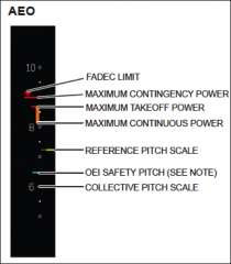
Take-off power (5mins) |
|
|
OEI CT limit on the FLI scale is indicated by: |
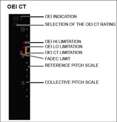
The bottom of the amber band & the FADEC stop symbol |
|
|
OEI LO Limit on the NG gauge is indicated by: |
A BROKEN RED line |
|
|
The FADEC Stop (topping) is indicated on the FLI scale by? |

A RED 'Diode' symbol |
|
|
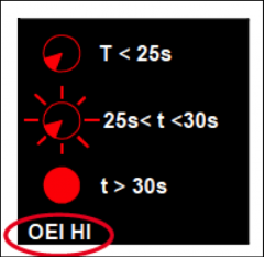
When operating in the OEI-HI power margin, the correct symbology is: |
|
|
|
When operating in the OEI-LO power margin, the correct symbology is: |

|
|
|
The aircraft CG datum is located? |
4.67 m FORWARD of the main rotor |
|
|
What are the boot loading limitations |
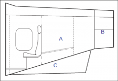
A (Top Shelf) : 250kgs B (Tail Cone) : 50kgs C (Main Lug) :250kgs A+B+C =400kgs max |
|
|
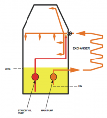
Capacity of the MGB oil system is? |
24 liters |
|
|
During normal system operation the MGB standby oil pump is prevented from delivering oil to the gearbox by? |
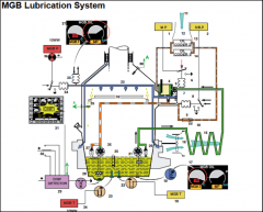
Check Valve located on the filter assembly. |
|
|
The DOOR/COWL caption on the CWP can be cancelled by? |
Close the relevant door |
|
|
The MGB LH Accessories gearbox drives? |
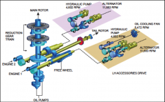
ALT 1 LH HYD Sys Pump MGB oil cooler fan |
|
|
The MP amber caption on the VMS Vehicle page indicates? |
Pressure in the main pump line is <3.7 bar |
|
|
With the MGB Main Pump operating normally and NO other captions, illuminations of the S/B P caption on the VMS Vehicle page indicates? |

The STBY pump is delivering <2.6 bar |
|
|
The correct action to take following illumination of the red MGP P caption on the CWP is: |
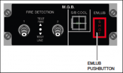
Reduce to Vy & operate the EMLUB system, land within 30mins. |
|
|
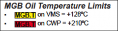
Temp threshold for illumination of the AMBER MGB T on the VMS Vehicle page? |
|
|
|
CHIP caption cleared on the VMS Vehicle page using the Fuzz Burner. Where has the chip been burnt from? |
The chip was on the sump chip plug on the MGB |
|
|
Following a MP caption on the VMS vehicle page the AMBER MGB T illuminates. The correct action to take is: |
Reduce to Vy and monitor the MGB temperature |
|
|
Operation of the MGB Standby Cooling System will cause? |
Some of the MGB Oil to be passed through the standby heat exchangers for cooling and then passed through the endoscopic |
|
|
The purpose of the over-pressure vent in the MGB is? |
To prevent the pressurisation of the MGB when the EMLUB system is in operation |
|
|
The EMLUB system consists of? |
11lts of glycol, injected with the assistance of P2.4 air (from the LH engine). (30mins). |
|
|
In the event of OEI, operations of the EMLUB system is? |
Not possible if the LH engine fails. |
|
|
The purpose of the heat exchanger in the EMLUB system is? |
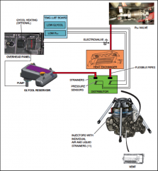
To reduce bleed air temperature below 80 degrees |
|
|
The correct response to the illumination of the Red MGB T caption on the CWP, verified by gauge indications is? |
|
|
|
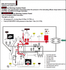
Illumination of the MGB EMLUB caption on the CWP indicates? |
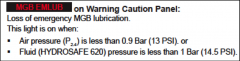
Failure of the EMLUB system OR the GLYCOL tank is empty |
|
|
With regards to the Rotor Brake, engine start is inhibited when: |
The rotor brake operating lever is in the 21 bar position |
|
|
The rotor brake receives hydraulic fluid pressure from: |
The LH hydraulic system |
|
|
The RB ON caption is illuminated: |
By a micro-switch at the RB puck calliper |
|
|
When must a high wind start procedure be carried out? |
When the wind speed exceeds 30kts |
|
|
During a high wind start with the Rotor Brake applied and the engine switch in the FLIGHT postion, what will occur? |
The engine will accelerate to IDLE |
|
|
The maximum NR limit for application of the rotor brake is? |
45 % |
|
|
The articulation of the MR blade sleeves is effected by? |
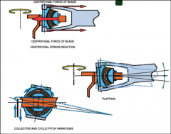
Laminated Spherical Thrust Bearings for ALL planes of movement |
|
|
IGB T caption will illuminate when the oil temperature in the IGB exceeds? |
110 degrees
|
|
|
TGB T caption will illumunate when the oil temperature in the TGB exceeds? |
94 degrees |
|
|
Conning angle of the MR blades is limited by? |
The centrifugal coning stop
|
|
|
The MR drag damping is effected by? |
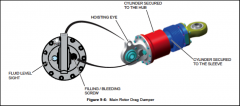
Hydro-elastomeric drag damper |
|
|
Automatic rotor tuning is effected by? |
Accelerometers built into the aircraft |
|
|
The LH Nr gauge is powered by? |
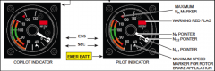
The Essential & Secondry bus |
|
|
The Nr LOW and HIGH aural waring thresholds are? |
95.5% 109.5% |
|
|
Power ON max continuous Nr is? |
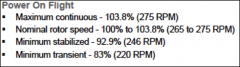
103.8% |
|
|
Power OFF minimum NR < 100KIAS? |
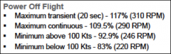
83% |
|
|
Failure of the Single Phase 26V AC Transformer is indicated by? |
0 volts indicated on the overhead panel with the rotary selector switch set to the 26V position. A STAB caption on the Radar display. |
|
|
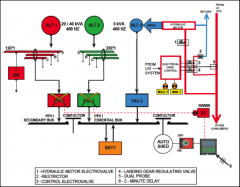
A short circuit on the ALT 1 distribution bus will be indicated by? |

ALT 1 BUS 1 TRU 1 |
|
|
Illumination of: TRU2, ESS BUS, BUS TIE and BATT+ captions indicate? |
DC essential Bus Short Circuit. |
|
|
What electrical consumers are lost with a single alternator failure? |
None (redundancy). |
|
|
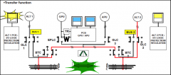
How are DC consumers supplied in the event of a short circuit on the AC Distribution Bus? |
Both ESS and SEC DC Bus Bars are supplied by the remaining TRU. |
|
|
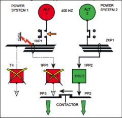
The EMERGENCY consumers are? |
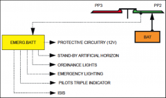
(From the Emergency Battery....) ISIS Ordinance Lights Emergency Lighting Triple Tacho |
|
|
In the event of a double Alternator Failure, what occurs in terms of load-shedding? |

PP3 (SEC BUS) load-shedding occurs automatically. |
|
|
Following a double TRU failure, indications that the Emergency DC Power Supply has come on line are? |
DC captions on the CWP extinguishes and a green FLOW light illuminates in the Emergency DC Power Supply selection switch. |
|
|
The amber TEMP caption in the overhead panel indicates? |
Battery is warm (>10 degrees case/internal temp differential) |
|
|
The minimum voltage for a battery start is? |
25 Volts |
|
|
AHRS 1 receives a reference signal from which component? |
26C AC Transformer |
|
|
Activation of the Emergency Gang-bar deselects what? |
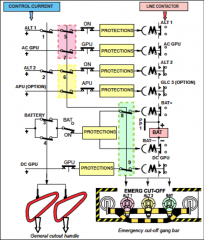
ALT 1 & 2 and the BAT + contactor |
|
|
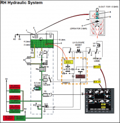
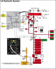
The LH Hydraulic system supplies which servo's? |

Upper bodies of the MR servos LH TR servos |
|
|
Illumination of the RH LVL caption on the VMS vehicle page indicates? |
Fluid in the reservoir has dropped to 2 liters or the socket is disconnected. |
|
|
Illumination of the APUMP caption on the VMS Vehicle page indicates |
The AUX pump has seized and an over-current is occurring (short circuit) |
|
|
The Auto-Pilot Hydraulics are lost when? |
LH LVL caption illuminates (4 lts) |
|
|
When the landing gear is lowered, the AUX pump will run: |
AUTOMATICALLY |
|
|
In the event of a Hydraulic leek occurring at the LH Hyd Pump, how will system pressure be assured> |
It is assured by the Main Pump 2 lt standpipe and the inline check valve. |
|
|
The AA.P caption will illuminate when system pressure in the AP Hyd pack: |
<70 Bar |
|
|
What indications and actions are required when the landing gear is lowered using the emergency landing gear extension system |
3 x greens within 2 minutes. The emergency landing gear extension handle needs to be pushed down to stop the pump after 2 minutes of operation (for cooling) |
|
|
A green PUMP light on the landing gear control panel indicates? |
The pump is running |
|
|
The undercarriage red LG warning light illuminates when? |
IAS < 60kts and undercarriage is retracted. |
|
|
Minimum GS for brake application |
35 kts |
|
|
A jammed main servo rotary distributor valve is indicated by? |
There is no cockpit indication. |
|
|
In the event of control failure, the TR control safety device will |
Set the tail rotor pitch to a value corresponding to 6-6.5 FLI (spring system) |
|
|
The Smart Electro-Mechanical Actuators have how much authority of the flight controls? |
+/- 7% |
|
|
In the event of LH Hydraulic system failure, a coupled approach is possible provide: |
The SEMA's are serviceable. |
|
|
Yaw / Collective coupling is provided such that: |
Permits yaw inputs generated by collective and the pedals do not move. |
|
|
The analogue trim actuators have how much control authority? |
100 % |
|
|
In the 7 tank fuel system, the correct number of jetpumps fitted are? |
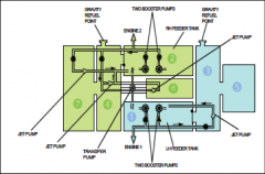
RHG x 3 LHG x 1 |
|
|
Low level fuel sensors are fitted in? |
Only the longitudinal tanks (< 71 kgs / 90 lts) |
|
|
During fuel transfer operations betwen longitudinal tanks, the HIGH level indicator light will illuminate when: |
The receiving longitudinal tank is full. |
|
|
With the AUTO TRANSFER switch in the OFF position on the fuel panel, the fuel quantity indication will be? |
LH and RH group quantity. |
|
|
Maximum permitted pressure for pressure refueling is? |
3.5 Bar |
|
|
During flight if fuel does not appear to transfer from the SPONSON tanks, the probable cause is: |
The REFUEL / DEFUEL switch is not in the OFF position |
|
|
The Engine Warning Repeater in the overhead quadrant will illuminate when? |
OIL P FADEC FIRE warnings illuminate |
|
|
The DIFF PWP caption on the CWP will illuminate when: |
Tq split >20% N1 split > 6% Engine Failure |
|
|
CHK TRQ caption will appear on the FLI scale when TQ split exceeds? |
5 % |
|
|
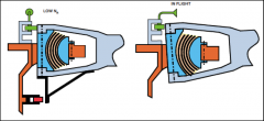
The engine bleed valve closes in normal operation at: |
90 % |
|
|
OIL P1 caption on the CWP will illuminate when engine oil pressure reaches? |
< 1.6 BAR |
|
|
In flight the illumination of the FADEC caption on the VMS indicates: |
Major governor failure |
|
|
Overspeed? |
117% - FADEC will shutdown engine |
|
|
Bleed valve offset mode control is effected by: |
APM's (in regards to IAS and RAD ALT) |
|
|
An engine automatic overspeed shutdown is confirmed by: |
The GOV light flashes when the starter selector is switched to shutdown |
|
|
How is Nr effected with an engine FADEC selector in the BACK UP position? |
The fuel metering is frozen, therefore Nr is regulated at 103.8% |
|
|
N1 speed signals are provided to the FADEC by? |
The engine driven Alternators |
|
|
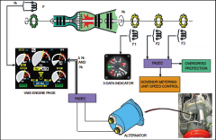
The triple Tach derives N2 speed signals sensed from? |

Toothed wheel (F1) fixed to the Free Turbine Shaft. |
|
|
Inadvertent operation of the 2nd SHOT fore bottle during an engine fire drill will cause: |
The fire bottle of the other engine to be discharged into the engine. |
|
|
The ISIS receives air pressure information from: |
Direct from the RH pitot tube. |
|
|
Three flashing indications at the top of the FND - P R Y: |
Are instructions to the pilot to TAKE MANUAL CONTROL. |
|
|
ECL INITIAL ACTIONS: ENGINE OVER HEAT DURING START OR SHUTDOWN |
1. Engine Control Switch - STOP 2. Crank affected engine UNTIL < 200°C |
|
|
ECL INITIAL ACTIONS: ENGINE BAY FIRE ON GROUND |
1. IF fire is confirmed visually….. a. Illuminated fuel shutoff valve - CONFIRM and PULL b. Fire extinguisher (1st shot) - ACTIVATE c. Engine control switch - STOP d. Booster pumps - OFF 2. IF fire indications persist…. a. Fire extinguisher (2ndshot) - ACTIVATE |
|
|
ECL INITIAL ACTIONS: ENGINE BAY FIRE IN FLIGHT |
1. Fire - CONFIRM 2. Illuminated fuel shutoff control - CONFIRM and PULL 3. Fire extinguisher (1st shot) - ACTIVATE 4. Engine control switch - STOP 5. Booster pumps (affected engine) - OFF 6. IF fire indications persist…. a. Fire extinguisher (2ndshot) - ACTIVATE b. Start timer. 12. If the fire indications persist for more than 1 minute after step 6 - a. LAND / DITCH IMMEDIATELY |
|
|
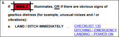
ECL INITIAL ACTIONS: MGB FIRE 1 AND2 |
1. LAND / DITCH IMMEDIATELY (EMERG LANDING POWER ON) NOTE: Only ONE MGB FIRE detection does not indicate a MGB fire. The systems run in parallel to each other an therefore TWO indication will be evident when there is a fire. |
|
|
ECL INITIAL ACTIONS: SMOKE AND / OR FIRE IN THE CABIN OR COCKPIT |
A)ACTIONS ON THE GROUND 1. Radio call Complete 2. If the source cannot be identified and isolated: a.General cut-out handle PULL b.Rotor brake APPLY c. Passengers Evacuate B) ACTIONS IN FLIGHT ECL |
|
|
ECL INITIAL ACTIONS: SINGLE ENGINE FAILURE IN FLIGHT |
1. Comply with relevant profile 2. Collective Maintain NR 3. If there are fire indications - 03 ENGINE FIRE IN FLIGHT |
|
|
ECL INITIAL ACTIONS: DUAL ENGINE FAILURE IN FLIGHT |
1. Collective - Lower immediately Warning: NR will decay rapidly even if recovery action is taken within 1 second. Maintain collective FULLY DOWN until NR recovers 2. Auto-rotate - 80 knots 3. If time persists: a. Both engine control switches STOP, then FLT NOTE: The start sequence will not begin untilN1 reduces to 10% 4. Landing Gear - Down overland / Up over water 5. Parking brake - OFF 6. Nose-wheel - LOCKED 7. Floats (overwater) - ARM /INFLATE (max 6500’/85kts) 8. Radio call - Complete 9. Satellite tracking - Switched to emergency 10. If neither engine will start Conduct a power of landing / ditching. CONSIDERATIONS: If neither engine has started by 1000’ RADALT, switch both to STOP and booster pumps OFF EOL - Progressive flare technique: At about 150’ above the surface, flare20° nose-up within 2 seconds and lower the collective. For landing, set 10° nose-up and use collective as required to cushion the touchdown. EOL – Constant pitch attitude technique: At 300’above the surface, set 10° nose-up and lower the collective fully. For landing, at about 50’ use the collective as required to cushion the touchdown. EOL – For both techniques: o As the collective is raised to cushion the touchdown, the collective to-yaw interlink will increase the tail rotor pitch, causing right yaw. Correct with left pedal and control roll attitude with cyclic to minimize drift. o Over water, try to reduce the G/S as much as possible and land with the wind 10-20° to the left. o Over land, at heavy weights, land at 20 knots or more if surface conditions permit. |
|
|
ECL INITIAL ACTIONS: FADEC FAILURE(MAJOR GOVERNING FAILURE) |
1. Collective - Maintain NR 2. If during takeoff - Continue takeoff |
|
|
ECL INITIAL ACTIONS: TOTAL LOSS OF MGB OIL PRESSURE |
MGB oil pressure < 0.4 bar 1. EMLUB SHOT Press 2. Timer Start (max 30mins) 3. Airspeed Set Vy 4. If the indications were simultaneous, or if MGB EMLUB illuminates: a. LAND / DITCH IMMEDIATELY |
|
|
Ground Clearance is |
.43 m |
|
|
Tail Skid clearance is |
1.12 m |
|
|
Max Floor Loading |
800 Kg/m sq |
|
|
Max Crosswind/Tailwind is |
Crosswind :25 kts Tailwind :20 kts |
|
|
Max Turbulence Speed is |
135 kts |
|
|
Rotor Brake limits are |
2 x 5 mins then 15 mins break (10 mins rotors running) |
|
|
Max Braking / Landing speeds are |
Landing Speed : 40 kts Braking Speed : 35 kts |
|
|
TAWS = Terrain Avoid Warn System is |
Enhanced Ground Warning System |
|
|
Starting Limits are
|
Max Continuous : 780 Max Transient : 830 - 5 sec Max Transient : 840 - 2 sec Auto Shut Down : 900
|