![]()
![]()
![]()
Use LEFT and RIGHT arrow keys to navigate between flashcards;
Use UP and DOWN arrow keys to flip the card;
H to show hint;
A reads text to speech;
36 Cards in this Set
- Front
- Back
|
Location errors refer to |
the geometric inaccuracies of digitized features |
|
|
Location errors can be examined by |
referring to the data source for digitizing |
|
|
Causes of Digitizing Errors |
Human Errors Scanning and Tracing Errors:Collapsed lines Misshapen lines Extra lines Duplicate lines Conversion Errors of Digitized maps to into real-world coordinates :Use a set of control points Errors will exhibit regular pattern Must re-digitized control points and rerun geometric transformation. |
|
|
new method for creating new spatialdata |
Using GPS and Satellite imagery data, |
|
|
When using GPS or remote sensing, the map scale does not contribute to thespatial data accuracy, only |
the resolution of the source data is relevant |
|
|
Spatial Data Accuracy Standards, three phases |
U.S. National Map Accuracy Standard 2. Accuracy standards for large-scale maps proposed by the American Society forPhotogrammetry and Remote Sensing in 1990 3. National Standard for Spatial Data Accuracy established by the FederalGeographic Data Committee in 1998 |
|
|
Standards for Horizontal Accuracy |
No more than 10% of well-defined map points shall be more than• 1/30 inch at scales larger than 1:20,000 (threshold of 40 feet on the ground)• 1/50 inch at scales of 1:20,000 or smaller (threshold of 167 feet on the ground) |
|
|
ASPRS (1990): Accuracy standards for large map scales |
Horizontal accuracy defined in terms of RMS• 1:20,000 scale maps RMS threshold of 16.7 feet (5.09m)• 1:2400 scale maps, RMS threshold of 2 feet (0.61m) |
|
|
Spatial Data Accuracy measures |
how close the recorded location of a spatialfeature is to its ground location |
|
|
Data Precision measures |
how exactly the location is recorded |
|
|
Distance measurements: |
• Decimal digits• Rounded to the nearest foot or meter |
|
|
Numbers can be stored as: |
Integers • Floating point• Single precision, with 7 significant digits• Double precision, with 15 significant digits |
|
|
Topological errors |
violate the topological relationships either required by a datamodel (e.g., the coverage) or defined by the user |
|
|
How many topological rules |
31 |
|
|
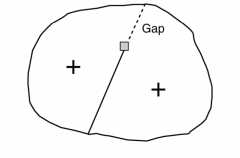
Topological errors with Line features include: |
• undershoot, (gap) • overshoot, (over extended line) • dangling node, results from undershoot or overshoot • pseudo node, appears along a continuous line and divides the line unnecessarily into separatelines. • direction error, (exp streams) • label error. If a polygon has two or more label point, it is an error |
|
|
Topological errors with Polygons: |
• Unclosed Polygons• Gaps between polygons• Overlapping polygons |
|
|
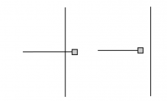
An overshoot (left) and an undershoot (right). Both types oferrors result in dangling nodes |
|
|
|
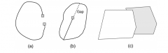
(a) An unclosed polygon,(b) a gap between two polygons, and(c) overlapped polygons |
|
|
|
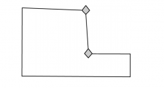
Pseudo nodes, shown by the diamond symbol, are nodesthat are not located at line intersections. |
|
|
|
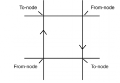
The from-node and to-node of an arc determine the arc’s direction |
|
|
|
Multiple labels can be caused by unclosed polygons |
|
|
|
Topological errors between layers include |
boundaries not coincident: between two polygons, or larger polygons notsharing boundaries with smaller polygons. • lines not connected at end points: between tow layers, example highwaysand roads are expected to connect perfectly across administrativeboundaries. • overlapping line features: example rail lines on highways, and line featuresnot covered by another set of line features (e.g. bus routes not covered bystreets) |
|
|
A powerful tool in ArcGIS for topological editing is |
cluster processing The processing uses a cluster tolerance, also called XY tolerance, to snap vertices (i.e., pointsthat make up a line) if they fall within a square area specified by the tolerance |
|
|
The default cluster tolerance is |
.001 m A cluster tolerance should not be set too large because a large cluster tolerance can unintentionallyalter the shapes of lines and polygons |
|
|
Vertices to be snapped can be in the same layer or between layers T/F |
T |
|
|
A map topology is |
a temporary set of topological relationships between the parts of features that aresupposed to be coincident.Therefore, editing using map topology can ensure, for example, that a land-use layer and a soil layershare the same study area boundary. |
|
|
To edit using map topology |
1- Create a map topology2- Specify the participating feature classes3- Define a cluster tolerance4- Use editing tools in the GIS package |
|
|
Editing with topology rules involves three basic steps |
1- Create a new topology by defining the participating feature classes. In afeature dataset,The rank of each feature classThe topology rule(s)The cluster tolerance 2- Validation of topology: this step evaluates the topology rule and createserrors indicating those features that have violated the topology rule.Topology rules will be saved to a topology layer 3- Using a topology layer for fixing errors and accepting errors andexceptions. (e.g. acceptable dangling nodes) |
|
|
Nontopological EditingBasic Editing Operations on existing features |
|
|
|
Nontopological operations can create new features by: |
Merging features: group selected line or polygon features into one feature (fig 7.19) Buffering features: to create a buffer around a line or polygon feature at a specified distance. Union features: to combine features from different layers into one layer Intersecting features: to create a new feature from the intersection of overlapped features indifferent layers. Other editing operations include:EdgematchingLine simplificationLine smoothing |
|
|
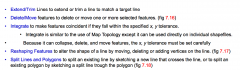
Edgematching |
matches lines along the edge of a layer to lines of an adjacent layerso that the lines are continuous across the border between the two layers Example: Edgematching is required for creating a regional highway layer that ismade of several state highway layers digitized and edited separately |
|
|
Shortest path analysis can only be used |
unless all errors between these differenthighway layers are removed |
|
|
Edgematching involves |
a source layer and a target layer |
|
|
Line simplification |
refers to the process of simplifying or generalizing a lineby removing some of its points |
|
|
Line smoothing |
refers to the process of reshaping lines by using somemathematical functions such as splines Line smoothing is more important for data display |
|
|
Douglas-Peucker algorithm |
used for line simplification, it works line byline and with a specific tolerance. |